传统人工钻井


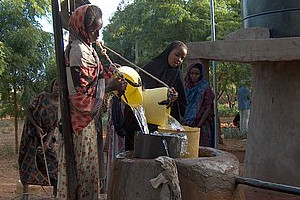
浅层井将水从含水层或人造含水层中抽出,例如在沙坝附近或池塘周围, 但不在河床中。它包括远离河流的井,或者包括从浅层含水层(以液压方式与河流相连)中取水的井。有时候,挖掘的洞大到可容纳人或者动物。
可使用手泵 或 小型电动泵抽取水。也可使用水桶和绳子,但会增加污染的风险。因此,应该提倡使用家用水处理。
适宜条件
- 砂砾层适合修建水井和井眼。其他选址可为花岗岩地区的风化岩石中,山区的山谷边缘或是河堤下有砂质沉淀物的河谷中。
- 应该避免在滞水含水层中挖水井,因为滞水含水层是浅层的含水层,水补给能力和储存能力有限。
避免污染
水井应远离污染源。对于微生物污染,进水口(滤网)与污染源(如厕所)的距离应该足够远,以降低污染风险。这样,病原体在地面的潜在传播时间至少有25天。传播时间受到多孔性、水力传导性(渗透性)和水力梯度的影响。对于中等大小、多孔性一般的沙子,病原体25天能传播大约30米,但是在沉淀物更粗的地方能增加到100米。但是,如果滤网入口的位置足够深,污染源到进水口的距离可以大大缩短,这是因为含水层纵向比横向的属性更多样,这意味着使用手泵挖掘的井眼与厕所的距离可以很近而被污染的风险很低。然而,滤网的深度必须随着抽水率的增加而加深。
| 优势 | 劣势 |
|---|---|
| - 人可进入水井,可日后再加深或轻松维护
- 可私人拥有或运作
|
- 难度更大,修建费时更久
- 修建过程中和过后存在更大的安全隐患 |
应对环境变化的适应性
干旱
干旱的后果: 水含水层可能会干涸,地下水位下降。
潜在的原因: 由于降雨减少,含水层的补给变少;人口增加,用水需求增加;含水层的面积——例如滞水含水层使用速度更快;水井在地下水位中深度不够。
增加 WASH 系统的适应性: 避免滞水含水层;将水井挖得更深——在地下水位中凿井沉箱排水井;使用伸缩衬砌进行后续加深;在旱季的后半段挖井;通过含水层补给管理(MAR)的井眼补给含水层;喷射水井底部以便加快补给速度;通过使用透水混凝土和多孔尖头钢管水平钻入含水层增加水量。
更多关于治理干旱的信息,请查看: 易干旱地区具有适应性的WASH系统。
修建、运作和维护
关于水泥的建议:建筑和隔板(例如水箱、大坝、水道和水井)出现裂缝的常见原因是在混合和使用水泥时出错。首先,很重要的一点是使用的成分一定要纯:干净的水、沙子和岩石,这些成分必须充分混合。第二,混合时使用的水尽量少:混凝土或水泥成形即可,宁可干点,也不要成为液体。第三,在固化过程中混凝土或水泥需要保持一定的水分,至少维持一周。同时,在固化过程中应该用塑料、大树叶或其他材料覆盖在引水建筑物上以保持水分。
Specific advice:


The basic elements of a hand-dug well are illustrated in Figure 5.3. The three main elements are:
A. The Well Head - this is the part of the well which is visible above the ground. It generally consists of a protective apron and a superstructure which depends on the type of extraction system in use.
B. The Well Shaft
C. The Intake - this is the part of the well in contact with the aquifer. It is constructed in such a way that water flows from the aquifer into the well, from where it can be extracted using a bucket, a pump or another method.
Hand-dug wells have a tendency to have very little water or even dry up in the dry season. This is largely to do with the fact that the intake area is not deep enough inside the dry season water table. Shallow aquifers tend to reflect recharge more sharply than deeper aquifers, resulting in water table fluctuations of several metres between seasons – these fluctuations need to be accounted for in the construction method. Several techniques can ensure that wells are sunk deep enough:
- Construct wells using a telescopic system, where an a permanent lining is created above the water table, together with a smaller diameter telescopic lining that enters the water table. The advantage of this system is that the smaller lining can be deepened at a later date without affecting the permanent lining and slab, e.g. in case the well was not sunk deep enough the first time. Another advantage is that the shaft has less chance to go out of vertical alignment during caissoning (where a shaft is sunk by digging).
- Use an effective method of de-watering during caissoning within the water table. Many hand-dug wells are dug without using a de-watering pump – consequently, the limit of penetration into the water table is about only 1 metre. Providing a de-watering pump will allow the shaft to be sunk deeper into the water table, but note:
- Type of pump depends on the height from ground level to water table – for a suction pump, the limit will be 6-7 metres, after which a submersible pump and generator needs to be considered. The type of pump should allow a certain amount of solid particles to be pumped.
- Attention needs to be given to safety considerations when using a motorized pump with someone digging in the well – engines should be located downwind so fumes do not enter the well, a 100 – 150mm vent pipe can be temporarily tied to the crossbeam to ventilate the well (in similar way to a VIP latrine), submersible pumps should be fitted with circuit breakers in case of electrical shortcuts to avoid electrocution, digger should be wearing construction harness attached to rope, and rescue & recovery action should be in place and practised regularly.
- Where using a de-watering pump results in subsidence around the well (in the case of flowing sands), another idea is to use a bailer instead of a pump. A bailer is normally used in percussion drilling, and consists of a heavy hollow metal tube with a valve on the bottom. When the bailer is dropped, sediment enters which does not come out when the bailer is removed. This method takes longer, but can be performed at ground level without a de-watering pump – since the water is not being pumped, flowing sand has less incentive to enter and the well shaft can sink slowly.
- Aim to dig wells during the latter half of the dry season when water table will be at their lowest.
Where deepening the well further is not possible due to water/sand ingress, jetting in the bottom of the well can provide a means of faster recharge into the well from deeper in the aquifer, meaning the well dries up less quickly. In this case a larger diameter screen (can be wrapped with geotextile) is jetted into the well base with the end protruding above the bottom of the well, after which it is plugged using a small bag of gravel.
Where wells still dry up in the dry season, recharge techniques could be used upstream of the well.
The use of porous concrete in part of the section of the well shaft which is underwater can help increase flow velocity into the well. Porous concrete is made using a of 1 : 1 : 4 (cement : sand : aggregate) and can be used for curved blocks or also for a central portion of any pre-cast concrete ring. Also perforated pointed steel pipes can be driven horizontally into the aquifer using a jack – this can also increase flow velocity into the well.
Simplify construction methods while getting a more robust end product in a safer fashion. Using lining & telescopic lining has the advantage that heavy lifting equipment for pre-cast rings is obsolete while procedures are inherently safer. Lining is made using one-skin moulds that hold concrete against the dug wall of the hole, while the telescopic shaft can be made from curved blocks built onto a foundation cutting ring – the blocks can be extended as and when necessary.
Costs
Hand-dug wells can provide a viable alternative to unhygienic, unprotected sources while avoiding the capital and maintenance costs associated with sophisticated drilling programmes or reticulated pumped systems. A range of lining types and water lifting technologies can be chosen to match the financial and management capacity of the participants in the water supply process.
Field experiences
The following projects are utilizing hand dug well techniques.
 Facilities Ibbagamuwa school Sri Lanka |
 Safe water for Wajir |
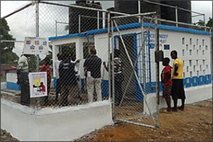 Urban WASH II in Monrovia |
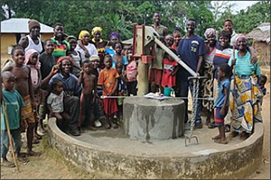 Senjeh Well Restoration |
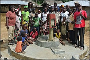 Gboto Well Restoration | ||
 WaterAid Rural WASH Project |
 Accelerating Sanitation and Water for All 1 |
 WASH services & capacity building Liberia |
Manuals, videos and links
- Well revival effort sees many other benefits A community drive to revive wells in Mokhla talab near Udaipur results in water security for longer periods of time as well as making leaders out of women.
- Experiments with 'community wells' Mobilized farmers in Dhule, Maharashtra, show how communities can use groundwater as a common resource in an organised and collective manner.
- Hand dug shallow wells (Skat). Includes construction information plus covers lining options. Also a good section on environmental, social, and cultural considerations. Swiss Centre for Development Cooperation in Technology and Management.
- Hand Dug Wells section of the Rural Water Supply Network website
- Consallen. An excellent guide to a relatively safe method of digging hand dug wells by the highly experienced British Drilling Company.
- Large Diameter Wells. An excellent but slightly outdated summary of hand dug wells by Koegel, made available by the UN FAO.
- Hand Dug Wells and Other Manual Methods to Dig a Well Have Been in Existence for Thousands of Years. Compares different methods of digging a well, includes hand-dug method.
- Old style of excavated wells in India: India Themes: Irrigation 1: Ancient Methods.
Acknowledgements
- CARE Nederland, Desk Study: Resilient WASH systems in drought-prone areas October 2010.
- Collins, Seamus, Hand dug shallow wells (Skat). Swiss Centre for Development Cooperation in Technology and Management. 2000.
