वाटर पोर्टल / वर्षाजल संचयन / सतही जल / तैरता जल-संग्रहण
| |
|
|
|
|
|
|
|
|
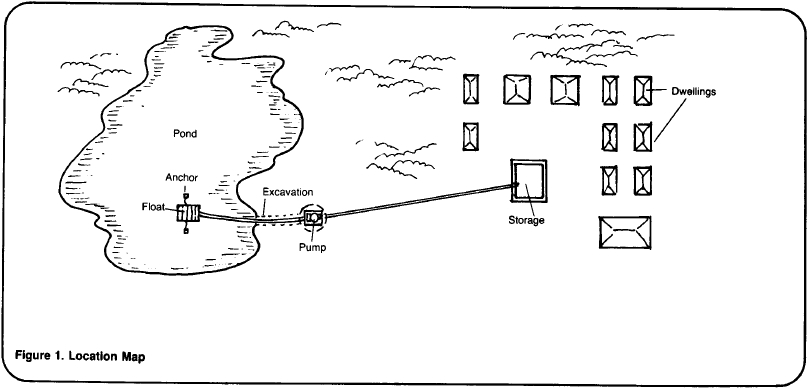
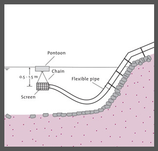
तैरता जल-संग्रहण पेयजल व्यवस्था में बहते पानी से निकासी नदी या झील की तलहटी के निकट होती है. ऐसा करने से एक सक्शन पंप का अंदरूनी हिस्सा जल स्तर के ठीक नीचे पीपा पुल से जोड़ दिया जाता है. यह पीपा पुल नदी या झील के किनारे पर या उसके करीब लगा होता है. इस पंप को नदी के किनारे पर या फिर उसी पीपा पुल पर स्थापित किया जा सकता है. पंप को उस पुल पर स्थापित करने का फायदा यह है कि सक्शन पंप काफी छोटा रहेगा और उसे स्थिर रखा जा सकेगा. अगर नदी की धारा से बड़ा कचरा बहकर आता है तो अतिरिक्त सावधानी बरतने की आवश्यकता होती है. अगर ऐसा नहीं हुआ तो वह क्षतिग्रस्त हो जाएगा. पीपा पुल बनाने के लिए स्टील या लकड़ी के फ्रेम की आवश्यकता होती है जिसे तेल के खाली ड्रमोंं, प्लास्टिक के खाली कंटेनरों या सील बंद स्टील की ट्यूब से जोड़कर बनाया जाता है.
Contents
किन तरह की परिस्थति में यह उपयुक्त रहता है
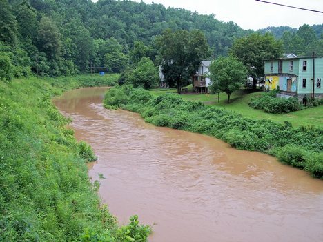
नदियां या झील
तालाब या झील में ऐसी प्रणाली लगाने से बेहतरीन गुणवत्ता वाला पानी हासिल होता है. उनकी स्थिति ऐसी होनी चाहिए कि वहां मानव अथवा पशुओं या फिर किसी भी तरह की गंदगी वाला पानी नहीं पहुंचे. इनटेक की समुचित स्थिति यह सुनिश्चित करती है कि समुदाय को साफ पानी मिल सके.
अक्सर तालाबों और झीलों में ऐसी व्यवस्था निर्मित करना महंगा पड़ता है. इस्तेमाल करने वाले जल स्रोत से जितनी दूर रहते हैं व्यवस्था उतनी ही महंगी पड़ती है. जहां संभव हो वहां स्रोत और इनटेक को एक दूसरे के और खुद समुदाय के करीब रहना चाहिए. खासतौर पर सूखे के समय समुदाय से दूर स्थित इनटेक से पाइप से पानी मिलने में दिक्कत आती है. इस मामले में यह सुनिश्चित करना चाहिए कि सूखे और बारिश के मौसम में पानी की मात्रा पहले से पता होनी चाहिए. ऐसा करने पर कम पानी या पानी की अनुपलब्धता के समय जल स्रोत में विविधता पैदा हो सकेगी.
जब भी संभव हो नदी में यह व्यवस्था वहीं पर करनी चाहिए जहां पानी का बहाव पर्याप्त हो. स्तर ऐसा हो जहां गुरुत्व के कारण पानी को पंप की आवश्यकता कम से कम हो. घनी आबादी वाले और कृषि क्षेत्र, पशुओं को पानी पिलाने के स्थान, कपड़े धोने के स्थान और नाली आदि के स्थान को दूर रखना चाहिए ताकि प्रदूषण कम से कम हो सके.
इनटेक का डिजाइन ऐसा हो कि गंदगी से जाम न हो बाढ़ जैसी स्थिति में भी ढांचा सुस्थिर रहे. जिन जगहों पर नदी के बहाव में पत्थर आदि नहीं आते हों वहां असुरक्षित इनटेक भी पर्याप्त है.
Resilience to changes in the environment
Drought effects on cement
Effects of drought: Badly made concrete or cracked linings (e.g. in tanks, dams, waterways, wells, and other structures).
Underlying causes of effects: Less water used for curing; Impure water used for mixing.
To increase resiliency of WASH system: Ensure adequate mixing, ratios, purity of ingredients; Minimize water content in mixture; Ensure adequate curing.
More information on managing drought: Resilient WASH systems in drought-prone areas.
Construction, operations and maintenance
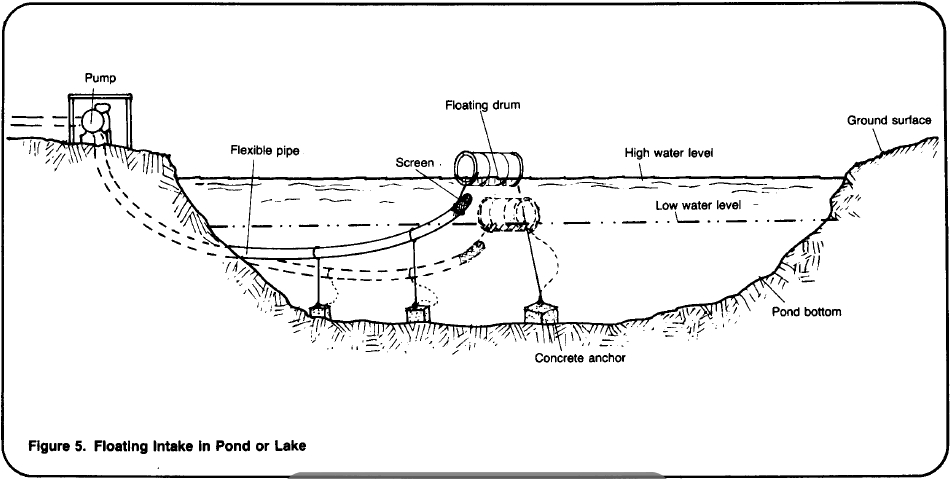
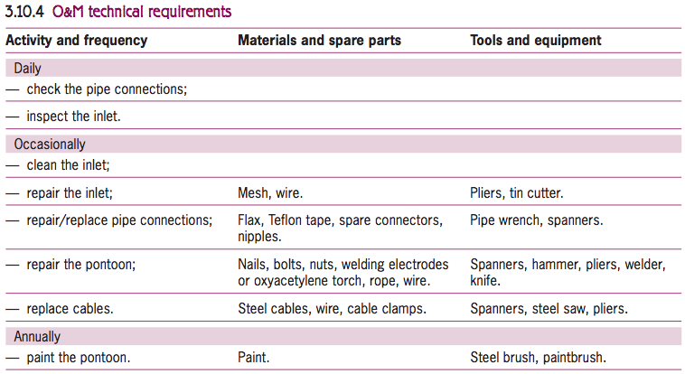
A floating-intake system is usually operated by a caretaker. The pump and inlet pipe must be checked before and during pump operation, and any obstructing debris removed and damage repaired. This is particularly important during the rainy season. Every day, the mooring cables should be checked and adjusted if necessary, and the flexible pipe connections checked for leaks. Any damage to the mooring or the pontoon structure must be repaired immediately, which may require the assistance of several people. Depending on the materials used, the pontoon should be painted regularly, at least once a year for steel parts.
Potential problems
— floating objects collide with the floating pontoon;
— the pipe connectors between the pontoon and the bank wear out;
— the lake or river water may be of poor quality.
Screens
In water supply engineering, screens are used for various purposes:
- Removal of floating and suspended matter of large size which otherwise might clog pipelines, damage pumps and other mechanical equipment, or interfere with the satisfactory operation of the treatment processes. Fixed screens are used for this purpose and they are cleaned on site by hand or mechanically.
- Clarification of the water by removal of suspended matter even of small size, to lighten the load on the subsequent treatment processes. In particular screens are used to prevent filters from becoming clogged too rapidly. Screening is done by passing the water through closely spaced bars, gratings or perforated plates. It does not change the chemical or bacteriological quality of the water. It serves to retain coarse material and suspended matter larger than the screen openings. Even when screened-out material forms a filtering mat of deposits, the screening still is purely of a mechanical nature. Bar screens usually consist of steel strips or bars spaced at 0.5-5 cm. If the amount of material ex-pected to be screened out is small, the bars are set quite steeply, at an angle of 60-75° to the horizontal, and cleaning is done by hand using rakes. If larger amounts will be retained, cleaning by hand should still be feasible; to facilitate the cleaning work, the bars should be placed at an angle of 30-45° to the horizontal.
The water should flow towards the bar screen at a quite low velocity, 0.1-0.2 m/s. Once the water has passed the screen, the flow velocity should be at least 0.3-0.5 m/s in order to prevent the settling out of suspended matter. In the openings between the bars the velocity of flow should be limited to a maximum of 0.7 m/s; otherwise soft, deformable matter will be forced through the screen openings. A clean screen will allow the water to pass with a head loss of only a few centimetres. However, the head loss rises sharply when the clogging of the screen builds up. Regular cleaning should keep the head loss limited to 0.1-0.2 m head of water. Allowing for delayed cleaning and mechanical failures, it is good practice to design a bar screen for a head loss of 0.5-1.0 m.
Manuals, videos and links
- Choosing where to place intakes. Water for the World.
- Constructing Intakes for Ponds, Lakes and Reservoirs. Water for the World.
- Maintaining intakes. US AID.
- Surface water intake and small dams. Nhamo Masanganise.
- Planning of Water intake structures for irrigation or hydropower. Helmut Lauterjung / Gangolf Schmidt. A Publication of GTZ-Postharvest Project, 1989.
Acknowledgements
- Brikke, François, and Bredero, Maarten. Linking technology choice with operation and maintenance in the context of community water supply and sanitation: A reference document for planners and project staff or (alternative link). World Health Organization and IRC Water and Sanitation Centre. Geneva, Switzerland 2003.
- Choosing where to place intakes. Water for the World.
- Surface water intake and small dams. Nhamo Masanganise.
