No. 6 pump
| |
|
|
|
|
|
|
|
|

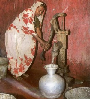
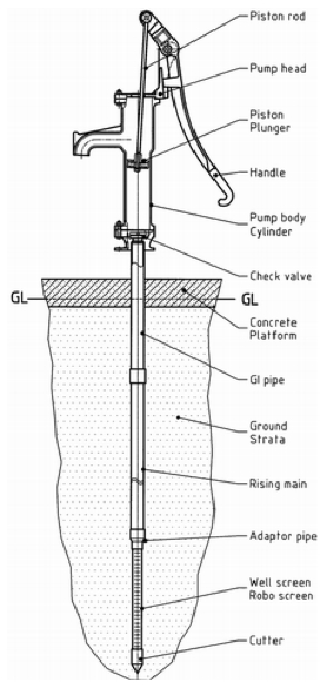
The No. 6 Pump is a lever operated suction pump for shallow wells. Typically, No. 6 Pumps are installed in collapsible tube wells with the screen extending to the coarse sand aquifer.
It is designed for family use, serving up to 100 persons. The maximum possible lift is 7 m. The No. 6 pump is a public domain pump defined by RWSN specifications. It is easy to install and has excellent potential for community based maintenance.
This pump is like all Suction Pumps limited to pumping lifts of a maximum of 8 m. It is not recommended to go deeper than 6-7 m. The No 6 Pump is not designed for a high daily output; it is rather a family or small community pump. If the foot valve looses its priming, water needs to be added to start the pumping again. This includes the danger of contamination.
The mode of operation of a Suction Pump
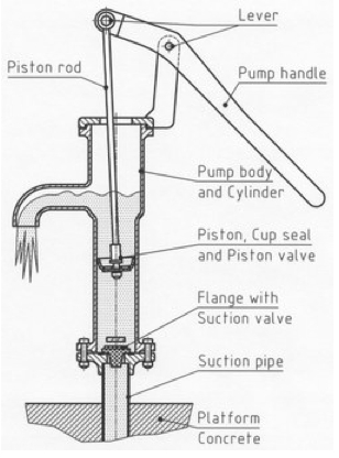
In a “suction” pump, the cylinder is above the water table, usually near the top of the pump head. The rising main extends below the water table. When the pump is operated, during the upwards stroke it appears that water gets “sucked up” through the rising main into the cylinder. Rather, the atmospheric pressure forces the water into the area of low pressure underneath the piston. The theoretical limit to which the atmospheric pressure can push up water is 10 meters. In practice, suction pumps can be used to lift water up to about 7 to 8 meters. A suction pump needs to be full of water before it can be operated. That means the pump needs to be primed. In regular practice, water has to be poured into the pump head by the operator, every time the pump is emptied by a leaking foot valve. Thus, the danger exists that the well can be contaminated through polluted water used for priming. The advantage of suction pumps is that the cylinder is normally above the level of the soil (above ground). For maintenance, the replacement of seals and valves can be easily performed with few tools.
Contents
Suitable conditions

Distribution: several millions in Bangladesh and India.
| Depths to be used: | 0 to 6 m |
| Cylinder diameter: | 89.0 mm |
| Maximum Stroke: | 215 mm |
| Approx. discharge (75 watt input): | at 5 m head: 3.5 m³/hour |
| Pumping lift: | 0 - 7 m |
| Population served: | 50 - 100 people |
| Households: | 5 - 10 hh |
| Water cons.: | 20 - 25 l/per capita |
| Type of well | collapsible tube well or dug well |
Construction, operations and maintenance

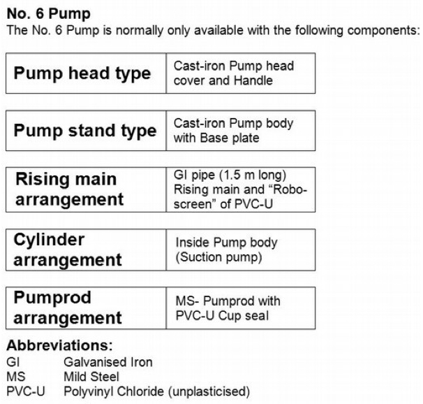
Pump head, body and handle are of cast iron, pump rods are of mild steel, suction pipe of PVC-U pipe, Plunger and check valve are of brass. This makes the No. 6 Pump reasonably corrosion resistant.
The installation of the No 6 Pump is easy and does not need any lifting equipment or special tools. The drillers who sink the tube well with the “sludging method” also install the pump.
This pump has an excellent “Community Management Potential”. Only two spanners are needed to repair plunger and foot valve. A village caretaker can perform all maintenance operations.

Acknowledgements
- Implementation Handpump Technology: No. 6 pump RWSN, 2009.