Water Portal / Rainwater Harvesting / Groundwater recharge / Wells, shafts, and boreholes
< Water Portal | Rainwater Harvesting | Groundwater recharge| |
|
|
|
|
|
|
|
|

Wells, shafts, and/or boreholes are holes (often human-made) in the ground at various depths used for the purposes of storing water for later use. Large diameter wells and smaller diameter boreholes can be used to directly recharge or dilute shallow aquifers where low permeability strata (rock) overlies the aquifers and where other infiltration methods are not effective. The important thing is that water of high enough water quality is used for this purpose. Although this method of recharge is practised with deep and high-yielding boreholes, this technique mainly describes recharge at the family level in areas where hand dug wells run dry at the end of the dry season or where groundwater is saline.
Wells that have run dry due to falling water tables from over-exploitation are also increasingly being used for this purpose. Recharge wells are advantageous when land is scarce. Water can be injected into a well or borehole and recovered from another, some distance from the first, to increase travel time and benefit from the water treatment capacity of the aquifer. This is referred to Aquifer Storage Transfer and Recovery (ASTR).
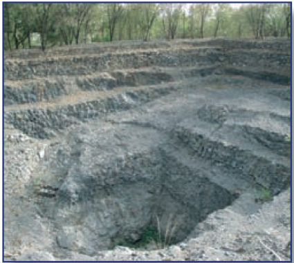
In loosely consolidated material, recharge pits and trenches are also used in cases where low permeability material overlies the aquifer, which occurs at trench-able depth, approximately 5-15m. Structures are excavated sufficiently deep to penetrate the low permeability strata, in order to provide direct access to the aquifer. Trenches or pits can be built to maximise the side-wall surface area and minimise the bottom surface area in order to facilitate horizontal movement of recharge water into the aquifer. The facilities should ideally be covered to keep out sunlight, animals, and people.
Suitable conditions
- Site only in areas where rainwater does not infiltrate fast enough where there is high runoff.
- Avoid where there is a risk of chemical contaminants entering the well, e.g. fertilizers and pesticides from agriculture, and when the final
water abstracted will be used for drinking, unless you have the ability to apply an appropriate filter.
| Advantages | Disadvantages |
|---|---|
| - Can assist recharge of shallow wells. Allows groundwater aquifers to be treated as massive storage tanks where in times of surplus, the aquifer can be recharged while in times of drought the water can be extracted. One example of this is the “water bank” concept for Windhoek’s water supply in Namibia. - Can reduce salinity in groundwater |
- Water quality requirements of recharge water are high - A good understanding of the hydrogeology of the aquifer is needed |
Resilience to changes in the environment
Drought
Effects of drought: Water levels reduce in wells & boreholes that are being recharged.
Underlying causes of effects: Less recharge.
More information on managing drought: Resilient WASH systems in drought-prone areas.
Floods
Shallow wells in areas with a high water table are more prone to contamination from flooding than deep boreholes. Wells near rivers can be contaminated and filled with sand during flash floods.
Construction, operations and maintenance
General advice on cement: A common cause of cracks in structures and linings (e.g. in tanks, dams, waterways, wells) is errors in mixing and applying the cement. First of all, it is important that only pure ingredients are used: clean water, clean sand, clean rocks. The materials have to be mixed very thoroughly. Secondly, the amount of water during mixing needs to minimal: the concrete or cement needs to be just workable, on the dry side even, and not fluid. Thirdly, it is essential that during curing the cement or concrete is kept moist at all times, for at least a week. Structures should be covered with plastic, large leaves or other materials during the curing period, and kept wet regularly.
Water source considerations
Water to be recharged should be high quality since blockage due to suspended sediment, microbial growth or chemical precipitation is more likely over the smaller infiltration area of a well or borehole. In Namibia, water from the water treatment works is further treated with granular activated carbon and chlorination before being injected to avoid such problems. In certain cases in India, open large diameter wells that ran dry due to falling water tables (resulting from over-exploitation) are being used to recharge shallow aquifers directly from runoff water that enters the wells – the problem with such structures is that there is no process of water infiltrating through the soil to the aquifer, which would not only reduce sediment and microbiological load, but also have potential chemical contaminants like nitrates and pesticides. Direct recharge of untreated water via open wells is therefore discouraged in preference to infiltration through a soil or sand layer. However, since silt and contaminants can more easily enter through a well, course gravel is sometimes filled into it to act as a filter, which can be replaced if clogging becomes severe.
One source of higher quality water, that is a realistic source of recharge water, is rainwater from roof catchments. This has been used to recharge shallow aquifers in Mozambique where groundwater was saline, with the result that the water was diluted. Ground runoff is also being used where potentially contaminated runoff water is used to recharge aquifers but where it still must infiltrate a certain amount of soil later – however the risk of aquifer contamination and screen blockage is increased. Hand dug wells that previously dried up now have water all year round – an evaluation after 3 years showed that out of 120 hand-dug wells that had recharge boreholes created close by to aid recharge, very few were drying up like they were before. In addition, families in the area were starting to replicate the system on their own.
Construction
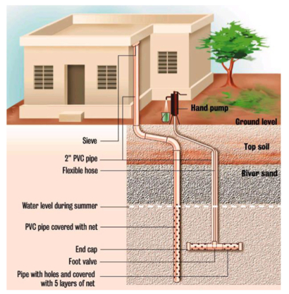
- The tubewell is sited 5 – 10 meters “upstream” from a well or borehole that dries up in the dry season, or in an area of saline groundwater.
- If taking water directly from a roof, ensure that the downpipe has a sieve on the inlet and a first flush system.
- A hole (e.g. 2”) is drilled with a step auger or a soil punch. The depth should be such that it passes the compact top layers and reaches the permeable layers – in general 4 – 6 meters is enough depending on the site.
- The recharge hole should not reach the groundwater layer aquifer to avoid contamination of the groundwater with surface water. Ideally the minimum distance should be 1.5m above the water table and 5 metres from an abstraction point such as a hand dug well. The water table can be known by observation in the hand-dug well.
- Test the recharge capacity of the hole after drilling by filling up the hole with water. It should absorb at least 2 litres per minute – if not, drill deeper.
- Plug the hole (e.g. with a cloth) to prevent debris entering, and make a small pond around the hole (0.5 – 1 metre deep, 1 – 5 metre diameter). Ensure the hole is on one side of this pond so that it can be accessed from ground level. The size of the pond depends on the required storage capacity, the infiltration capacity of the soil and the rainfall pattern but in general will be between 1 – 10m3.
- Remove the plug and fill up the hole with gravel (5 – 30mm) until 2 metres from ground level.
Installing a filter
Install a filter which will screen out solid particles (e.g. leaves etc). This can be done using a PVC screen or sand filter, depending on the incoming water quality.
PVC filters are used in combination with ground runoff:
- In general it is best to reduce the speed of the water as much as possible to avoid the pond from filling up with sand and clay – this can already be done by planting grasses and other catchment methods (for methods, see Natural ground catchment and Open water reservoir).
- The PVC filter pipe can be between 25 – 100mm and acts as a screen to allow water to infiltrate into the gravel layer (i.e. PVC has horizontal slots cut in the side).
- The pipe protrudes just above the base of the pond.
- A PVC cover piece is fabricated which is closed at the top and flares at the base so that it fits over the protruding pipe – the purpose of the cover is to prevent too many sediments entering the pipe and is removed only 4 hours after rainfall. Once water has infiltrated, the cover is replaced until the next time.
- Cleaning involves swabbing the inside of the PVC with a cloth.
Sand filters can also be used instead of the PVC filter system – this is where sand replaces the need for a cover piece and the need to wait 4 hours. It can be used with rooftop catchments where no surface runoff enters the hole, and could be done with or without a PVC pipe.
Water extraction
- Water can be abstracted from the same borehole or well used for injection/recharge – this is called Aquifer Storage Recovery (ASR).
- Water can also be abstracted from a separate borehole or well than the one used for injection/recharge – this is called Aquifer Storage Transfer and Recovery (ASTR). In the case of roof rainwater recharge systems in Mozambique, this design was used where the pump would extract water from a separate place close to the screen connected to the roof catchment.
Maintenance
Some chemical pretreatment of the water may be required to prevent flocculation of iron, CaCO3, etc. and chlorination of other disinfection may be needed to prevent microbial growth. Clogged wells may need to be recovered at regular intervals using surging and pumping to remove fines and bacterial growth physically and the use of a wetting agent to remove air in an air-clogged well. Carbonate aquifers exhibit the least amount of clogging due to the gradual dissolution of calcite by a slightly acidic injectant, if periodic backflushing is observed.
Field experiences
 Community Water and Sanitation Project |
 Scale up of Sustainable Water Access |
Manuals, videos and links
- Well revival effort sees many other benefits A community drive to revive wells in Mokhla talab near Udaipur results in water security for longer periods of time as well as making leaders out of women.
- Experiments with 'community wells' Mobilized farmers in Dhule, Maharashtra, show how communities can use groundwater as a common resource in an organised and collective manner.
- Battling water scarcity with borewell recharge
- Namibian capital needs "water banks" for dry times. Reuters. 26 Oct 2011.
- Planning Water Resource Management: The Case for Managing Aquifer Recharge, by E.C. Murray and G. Tredoux.
- Augmenting groundwater: The basics on how to construct a recharge well. India Water Portal. Includes materials and costs.
- Commercial product: PERMAWELL. Made by AquaSanTec.
Acknowledgements
- CARE Nederland, Desk Study: Resilient WASH systems in drought-prone areas. October 2010.
- Gale, Ian, Strategies for Managed Aquifer Recharge (MAR) in semi-arid areas. UNESCO's International Hydrological Programme (IHP), 2005.
- Water: The Water Crisis. Unite for Sight.
